Free UK delivery on orders over £150
A valve demands three torques: breakaway (to start moving), running (through mid-stroke) and seating (to close). The actuator must exceed each at the matching point in the stroke.
Pneumatic actuator torque scales with supply pressure and piston area, so size at the lowest pressure the valve will actually see, not the compressor setting.
Torque varies through the stroke. A rack-and-pinion actuator gives roughly constant torque, while a scotch yoke gives high torque at the ends and low torque in the middle.
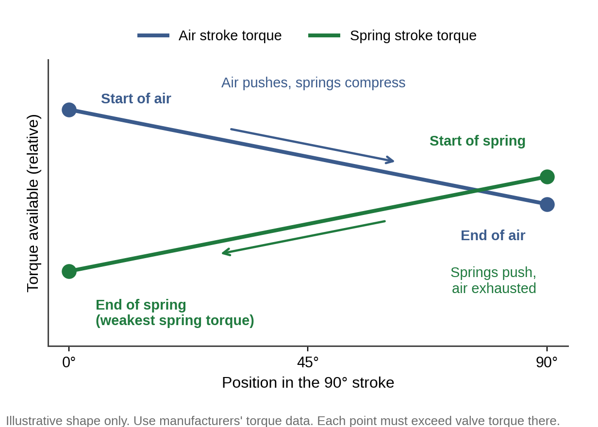
Spring-return actuators have two torque checks: the air stroke and the spring stroke. The weakest spring torque is at the end of the spring stroke.
There is no universal safety factor. Published guides range from about 10% to 50%, so use your manufacturers’ recommendation.
Oversizing is not safe either. The actuator’s maximum output must stay below the valve’s maximum allowable stem torque.
Most actuator problems are sizing problems. An actuator that has enough torque to open a valve but not to close it, or that has plenty of torque on paper but not at the air pressure the valve really sees, will stick, leak or fail to seat. Getting the sizing right means knowing what torque the valve demands, what torque the actuator really delivers at each point in the stroke, and how much margin sits between them.
This guide explains the three torques a valve demands, how actuator torque is produced and how it varies through the stroke, a step-by-step sizing procedure with a worked illustration, how spring-return actuators differ, and why published safety factors vary so much. It ends with fault-finding for an actuator that won't seat a valve. It focuses on pneumatic quarter-turn actuators, with notes on electric.
Valve actuator sizing is matching an actuator’s torque output to the torque the valve needs, at every point in the stroke and under the worst realistic conditions. An undersized actuator can stick or fail to seat the valve. An oversized one wastes air and can overtorque the valve.
Sizing means matching the actuator's output to the valve's demand at every point in the stroke, with margin to spare. The mismatch can go either way. An undersized actuator sticks, leaks or fails to seat. An oversized one wastes air and money, and the extra torque can damage the stem or the valve's internals.
Torque
What it is
Where it occurs
Breakaway (opening)
Running
Seating (closing)
Different valve types have different torque signatures, so the numbers must come from the valve manufacturer, for your conditions. Torque rises with:
• Differential pressure across the valve at the moment it operates.
• Seat and packing friction, including a switch to a higher-friction packing.
• Media, temperature and viscosity, which change friction and sealing force.
• Time at rest. A valve that stays still for long periods can have a higher breakaway torque.
• Seat wear. Over the years, seating torque can rise.
Manufacturers often publish torque for a given pressure in clean water service. Treat that as a starting point, and ask for your service conditions.
A pneumatic actuator turns air pressure into rotation. The piston force is pressure multiplied by piston area, and torque is that force multiplied by the distance over which it acts about the shaft. In simple terms, torque scales with supply pressure and piston area, and the geometry decides how the distance changes through the stroke.
That geometry gives two common torque patterns:
Rack and pinion
Scotch yoke
How it converts motion
Torque through 90°
Sizing values
Suits
Watch for
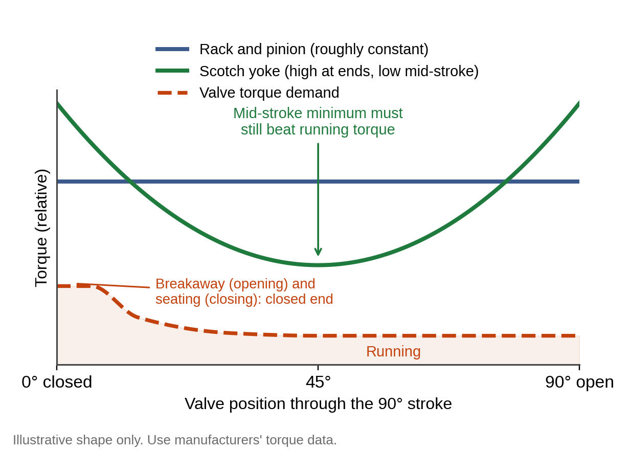
Work through the steps below. Always use the manufacturers' own torque tables and recommendations, because torque curves, safety factors and limits differ between products.
Step
What to do
Why it matters
1. Get the valve torques
2. Apply the safety factor
3. Find the real minimum air pressure
4. Read the actuator’s torque
5. Check both strokes on a spring-return actuator
6. Check the upper limit
7. Check the interface
8. Check duty and fail action
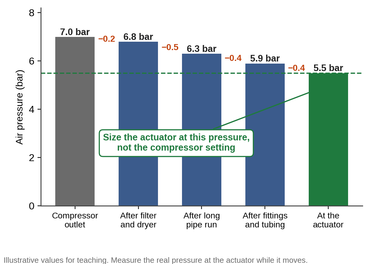
The numbers below are invented to show the method. Never size from them. Use your manufacturers' data.
Item
Illustrative value
Result
Valve breakaway torque (from the valve maker)
Safety factor recommended for the pairing
Minimum air pressure at the valve
Maximum air pressure at the valve
Valve MAST (from the valve maker)
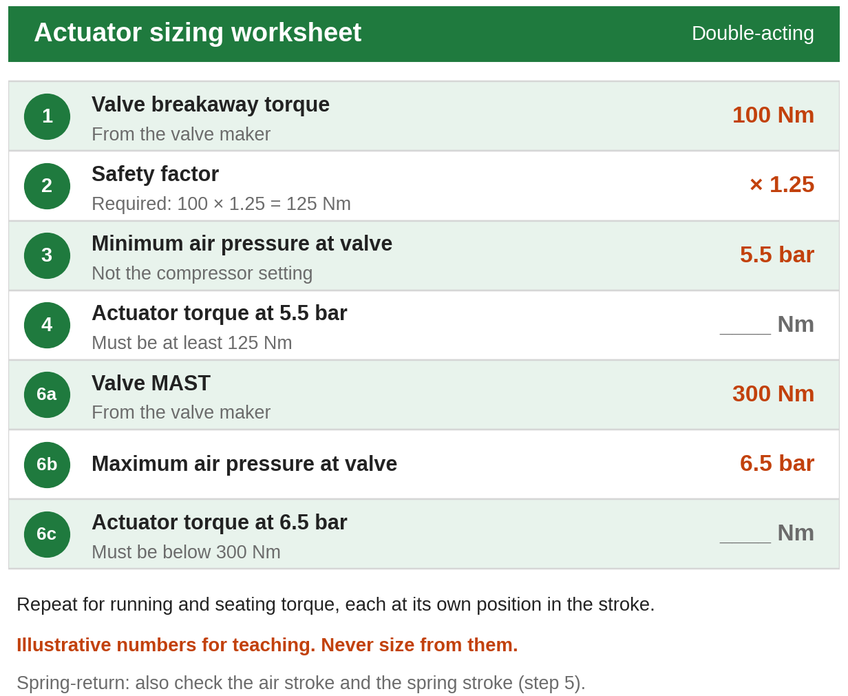
The chosen actuator must deliver at least 125 Nm at 5.5 bar at the stroke position where the valve needs it, and no more than the MAST at 6.5 bar. The same check is then made for the running and seating torques, each at its own position in the stroke.
A spring-return, or single-acting, actuator uses air to move the valve one way and springs to move it back, so it can drive the valve to a fail-open or fail-closed position when air is lost. That adds a second torque check, because the springs oppose the air on one stroke and provide the force on the other.
Term
Meaning
Air stroke
Spring stroke
Start and end of air
Start and end of spring
For a valve that must close by spring on loss of air, the check that matters is the spring torque with the springs fully extended, because that is what is available to seat the valve with no air. The valve's torque must be lower than each corresponding actuator torque, and the actuator's highest torque must stay below the MAST.
Published sizing guidance doesn't agree on one safety factor. One manufacturer's guide suggests at least 15% for double-acting and 10% for spring-return actuators. Another uses 20%. A worked example from a third uses 1.2 for double-acting and 1.5 for spring-return. Another recommends at least 30%. Differences like these come from the actuator type, how well the valve's torque is known, and the service.
The practical rule is simple. Use the factor that the valve and actuator manufacturers recommend for your pairing and service, apply it to the valve's published torque, and record which factor you used.
Actuator
On loss of air or power
Notes
Double-acting pneumatic
Spring-return pneumatic
Standard electric
Fail action is a process safety decision, so settle it with the process requirements first, then size for it. On modulating duty, add a positioner. On safety valves, partial-stroke testing can confirm an actuator isn't stuck without taking the valve out of service.
• Differential pressure across the valve increases.
• The valve trim or seat material changes.
• The instrument air pressure is reduced.
• The valve is repacked with a higher-friction packing.
• The valve operates at a much higher cycle rate than planned. High-cycle duty can need derated output, since cycle life is separate from static torque.
Actuator failures rarely come without warning. Slow stroke times, air leakage, positioner drift and rising breakaway torque as seats wear are the usual early signs.
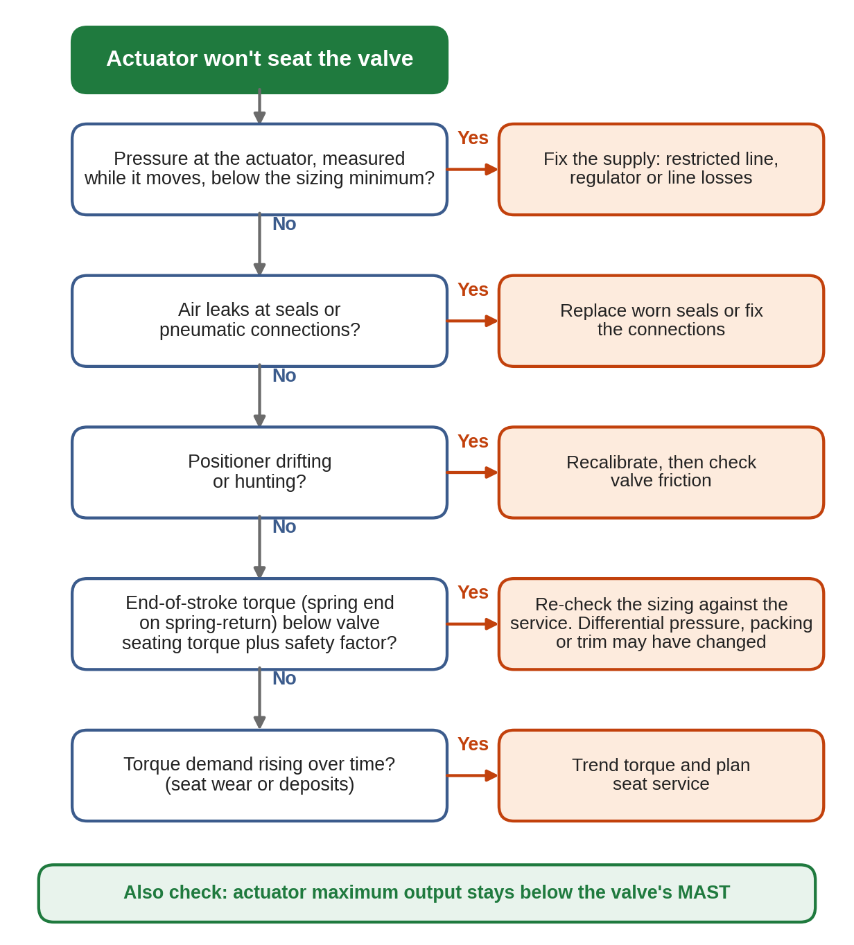
Symptom
Likely cause
What to check
Opens the valve but won’t close it fully
Valve sticks mid-stroke
Slow stroke times
Air leaks
Positioner drifts or hunts
Torque demand rising over time
Stem damage
Mistake
What happens
How to avoid it
Sizing at the compressor pressure
Using a rule-of-thumb safety factor
Checking only breakaway torque
Ignoring the spring stroke
Ignoring MAST
Not re-checking after changes
Assuming fail-safe action
Valve actuator sizing is matching an actuator’s torque output to the torque the valve needs, at every point in the stroke and under the worst realistic conditions. An undersized actuator can stick or fail to seat the valve. An oversized one wastes air and can overtorque the valve.
Breakaway torque is the torque needed to start moving a valve from rest. It is usually the highest torque the valve demands, because it must overcome seat friction and the effect of differential pressure. It is typically highest at the closed position, so it is the first value to check when sizing.
Breakaway torque starts the valve moving, running torque keeps it moving through mid-stroke, and seating torque is needed at the end of the stroke to close the valve against the seat. The actuator must exceed each of them at the matching point in the stroke, after allowing for a safety factor.
There is no universal figure. Published sizing guides use factors from roughly 10% to 50%, depending on actuator type and service. Apply the factor your valve and actuator manufacturers recommend for your application to the valve’s published torque, rather than a rule of thumb.
Actuator torque scales with supply pressure, and the pressure at the valve can be lower than the compressor setting. Sizing at the lowest pressure the valve will actually see means the actuator still delivers enough torque when the supply sags.
A double-acting actuator uses air to move the valve in both directions and stays in place if air is lost. A spring-return, or single-acting, actuator uses air in one direction and springs in the other, so it drives the valve to a fail-open or fail-closed position when air is lost.
Maximum allowable stem torque is the torque that would permanently deform or break the valve stem. The actuator’s maximum output at the maximum supply pressure must stay below it, otherwise an oversized actuator can damage the valve it is meant to operate.
A scotch yoke’s mechanical advantage changes with the yoke angle, so its torque is highest at the start and end of the stroke and lowest in the middle. A rack-and-pinion actuator gives roughly constant torque through 90°. The valve’s torque pattern should be matched to the actuator’s.
A standard electric actuator fails in place on loss of power, because the motor and gearbox hold position. True fail-open or fail-closed action needs an added battery, capacitor or spring-return unit, which adds cost compared with a pneumatic spring-return actuator.
Re-check it whenever differential pressure increases, the valve trim or seat material changes, the air supply pressure is reduced, or the valve is repacked with higher-friction packing. Seat wear over the years can also raise seating torque, so periodic torque checks suit critical valves.
On modulating duty, yes. A positioner holds accurate valve position across the stroke, which the flow relationship depends on. On simple on/off duty, a positioner is often unnecessary.
ISO 5211 specifies the flange and driving-component dimensions used to attach part-turn actuators to industrial valves. It helps the actuator mount and couple to the valve, but torque, stem size and maximum allowable stem torque still need checking separately.